CARRIDA Cam Dragon+ Series Operating Manual
| Revision: | 2.0 |
|---|---|
| Date: | 2024-03-06 |
| Contact: | support@carrida-technologies.com |
| Copyright: | 1996-2023 CARRIDA Technologies GmbH, Ettlingen, Germany |
| Author: | CARRIDA |


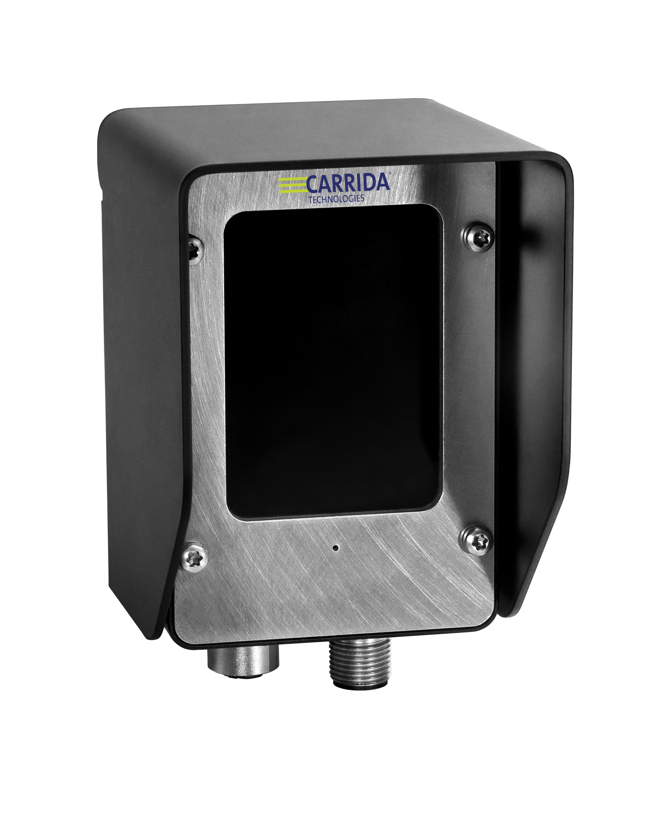
Table of Contents
1 General Information
The CARRIDA Dragon cameras have been designed for high resolution image processing with a very small form factor. They are the ideal compromise between high performance and low system costs.
Based on a quad-core processor ARM® Cortex®-A53 with 1.2 GHz the CARRIDA Dragon cameras offer ANPR solutions at high-speed in real-time.
All cameras are equipped with a battery backed real time clock and come with several programmable input/output signals, with trigger input and flash trigger output, as well as a 100 MBit Ethernet interface. Different CMOS sensors with global shutter are available (the image resolution can be changed to the ROI required).
1.1 Technical Specifications CARRIDA Cam Dragon+
| Component / Feature | Specification |
|---|---|
| CMOS Sensor |
|
| Active pixels |
|
| Pixel size |
|
| Active sensor size |
|
| High-speed shutter |
|
| Low-speed shutter |
|
| Integration | Global shutter |
| Picture taking | program-controlled or external high speed trigger, jitterfree acquisition
|
| A/D conversion | 8 Bit |
| Input LUT | no |
| Processor | Quad-Core ARM® Cortex®-A53 with 1.2 GHz |
| RAM | 1 GB DDR-SDRAM |
| Flash EPROM | 16 GB flash memory (nonvolatile) industrial eMMC |
| Process interface | 2 inputs / 2 outputs, outputs 200 mA each |
| Trigger Input | 1 dedicated picture trigger input. Any of the available PLC inputs can be chosen as an optional trigger input source. |
| Trigger Output | 1 default trigger output on TrigOut pin. Any set of the available PLC outputs can be chosen as trigger output. |
| Ethernet interface | 100 Mbit / 10 Mbit |
| CE certification | CE Certification from Vision Components |
| Storage Conditions | Temperature: -20 to +60 deg C, Max. humidity: 90%, non condensing. |
| Operating Conditions |
|
| Power Supply | 24V DC
|
| Power Consumption | 7.5 W typical |
| Heater | 23 W |
| Protection | IP67 |
2 Camera Interfaces
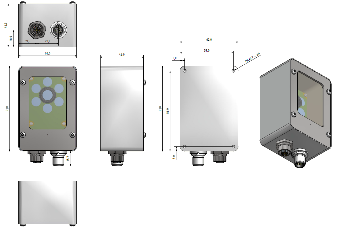
Connector Positions
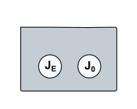
The CARRIDA Cam Dragon+ camera incorporates the following connector interfaces:
| Connector | Description |
|---|---|
| J0 | Power Connector |
| JE | Ethernet Connector |
The pin assignments, electrical specifications as well as available accessories are shown for each interface connector in the following sections.
2.1 Power Connector J0
2.1.1 J0 Pin Assignment
| Camera Socket Rear View | Pin | Signal | Level | Cable Standard Color |
|---|---|---|---|---|
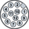 |
1 | Main Power Supply | +24 V | brown |
| 2 | Common Ground | GND | blue | |
| 3 | PLC In0 | +24 V | white | |
| 4 | PLC Out0 | +24 V | green | |
| 5 | PLC In1 | +24 V | pink | |
| 6 | PLC Out1 | +24 V | yellow | |
| 7 | black | |||
| 8 | grey | |||
| 9 | red | |||
| 10 | TrigIn | +24 V | purple | |
| 11 | TrigOut | +24 V | grey/pink | |
| 12 | red/blue |
2.1.2 Electrical Specification: Camera Power Supply
| Nominal Voltage | 24 V |
| Nominal Power Consumption [1] | 7.5 W |
| Minimum operational voltage (including ripple) | 9 V |
| Minimum nominal Operating voltage and corresponding current | 12 V, 625 mA [2] |
| Maximum nominal Operating voltage and corresponding current | 24 V, 312 mA [2] |
| Maximum operational Voltage (including ripple) | 30 V |
Power must be connected to pin 1&2 of the ST 1 connector.
Camera power is regulated, so only an unregulated power source of 12 V to 24 V is required. The camera is, however, very sensitive to power supply interruption. Please make sure that the voltage never exceeds the limits of < 9 V, > 30 V even for a short period of time.
Note that the LED IR illumination of the camera may not be operational at a power supply <24 V.
| [1] | Typical power consumption. |
| [2] | (1, 2) Power consumption may change with processing load and FPGA revision. |
2.1.3 Electrical Specification: Digital PLC I/O
| Separation of PLC/trigger output voltage | PLC outputs supply not separated from power supply |
| PLC Input Voltage | 5 - 24V |
| Input Current (max) | 3mA @ 24V |
| PLC Output Voltage | 24V |
| PLC Output Current (max) | 2 x 200 mA |
| Max Current for 1 Power / PLC connector pin | 200 mA |
| Power failure detection | Yes, overcurrent protection with polyfuse on each output |
Warning
 If power failure is detected, each PLC output may switch off
regardless of their output state.
If power failure is detected, each PLC output may switch off
regardless of their output state.
2.1.3.1 Connection of PLC inputs CARRIDA Cam Dragon+ Series
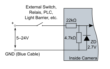
Connection of PLC Inputs
2.1.3.2 Connection of PLC outputs CARRIDA Cam Dragon+ Series

Connection of PLC Outputs
2.1.4 Electrical Specification: Trigger I/O
2.1.4.1 Connection of Trigger Input
Connection of Trigger input
2.1.4.2 Connection of Trigger Output
Connection of Trigger output
Warning
Do not connect inductive loads to TrigOut output!
2.2 Ethernet Connector JE
2.2.1 JE Pin Assignment
| Camera Socket Rear View | Pin | Signal |
|---|---|---|
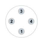 |
1 | Tx+ |
| 2 | Rx+ | |
| 3 | Tx- | |
| 4 | Rx- |
Note

- The Ethernet connector has an ESD input protection.
2.3 Realtime clock and backup battery
The board contains a realtime clock (RTC) with battery backup. The RTC is set during manufacturing to the current date and time. For backup a rechargeable lithium coin cell battery is used. This battery is charged to only about 10 percent of the nominal capacity on delivery and may be empty after a prolonged period of storage. We recommend charging the battery for at least 50 hours and setting the RTC (Linux command: hwclock and date) when the board is first used (battery charges automatically when the system is powered on). The battery contains so little lithium, that it is not listed as a hazardous device for the environment and the flight export regulations. For details please refer to https://industrial.panasonic.com/ww/products/batteries/secondary-batteries/coin_rechargeable_lithium/coin-type-rechargeable-lithium-batteries-ml-series/ML621
| Battery Manufacturer | Panasonic |
|---|---|
| Battery Type | ML621 |
| Nominal Voltage | 3V |
| Nominal Capacity | 5 mAh |
| Charging Time for 100% Capacity | 100h |
| Charging Time for 80% Capacity | 50h |
| Backup Retention Time for 100% Charged Battery | 200 days |
Note
To check if the hardware clock is set appropriately, scan the output of the following linux shell command:
dmesg | grep rtc
One response line may contain the following message:
[ 0.322074] rtc-ds1374 0-0068: oscillator discontinuity flagged, time unreliable
This indicates low battery status or battery discontinuity.
To set the hardware clock it is necessary to set the software clock first:
date -s "2017-11-21 11:47:00"
Then the software clock time is transferred to the realtime clock by the following command:
hwclock -w
2.4 Built-in heater
The CARRIDA Dragon camera contains a built-in heater which is automatically activated when necessary. The following table and diagram show the behavior of the heater.
| Temperature | Heating power | CPU |
|---|---|---|
| T < -5 °C | 100 % (23 W) | Off |
| -5 °C < T < 5 °C | 20 % (4.6 W) | On |
| T > 5 °C | 0 % | On |
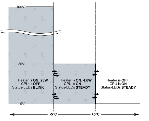
Behaviour of the built-in heater
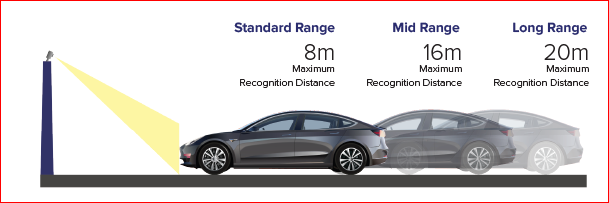
3 Appendix A: Lens options
The CARRIDA Dragon Camera can be equipped with three different lenses so that you can optimize its field of view depending on the expected distance of vehicles. The following figure depicts the available options: